|
Introduction
Have you ever wanted an
airport diagram and just couldn't lay your hands on it?
Have you spent 45 minutes scouring the web for one,
finding everything you could possibly want to know about
the airport in question, including the phone numbers of
all the rental car agencies and a colour-coded map of the
atrium shops, but no airport diagram?
This may help.
With just a little effort and a short learning curve you
can produce a reasonably high-quality diagram for any
airport in FS in a remarkably short time. Interested?
I thought you might be!
What you need is my easy to follow DIY instructions,
good luck! If you get any problems and want to ask
questions or just want to download some ready-made
plates then visit the forum
here.
|
I've gotten in the habit
of having hard copies of the airport diagrams for both
departure and destination airports whenever I fly a
"structured" flight, i.e. something other than just
drilling holes in the sky; the kind of flight where I
actually know ahead of time where I'm going to end up.
I think maybe what led me to that was the vaguely
shameful feeling that I would get whenever I had to turn
on the progressive taxi option in Flight Simulator. You
know the situation -- "... taxi to and hold short of
runway 33 Right via taxiways Mike, Alpha 4, Victor,
Sierra, Sierra 3, runway 24, Romeo, Tango 1." I hated
to do it but sometimes I had no choice but to reach for
the "Ladies Aid" by lighting up those hated magenta
crutches.
In an effort to avoid
that, I began to include hard-copy airport diagrams in
my pre-flight planning packets. I make a big production
of planning my Cargo Pilot flights in particular. It’s
very satisfying to be able to land at a complex,
unfamiliar airport at night and make my way to where I
need to go without any help.
Unfortunately,
good-quality airport diagrams don't always come easily
to hand. For most medium and large US airports the NACO
site…
http://www.naco.faa.gov/index.asp?xml=naco/onlineproducts
…is one-stop (free)
shopping for not only airport diagrams, but DPs, STARs,
approach plates, and assorted other reference data. For
almost anywhere else, however, things are a little more
difficult to find.
Oh, sure, there are those
little 1 1/4" square graphics in the bottom corner of
many approach plates. I've tried scanning them and
blowing them up, adding more data when I had it --
entirely unsatisfactory. What to do?
This method was a
forehead-slapper when I finally stumbled over it. I’m
embarrassed how long it took me, but I realized one day
while using AFCAD that a good part of what I needed was
staring me in the face. I set out then to try to make
serviceable airport diagrams beginning with the AFCAD
image of the airport. After a little fooling around I
had a good product in a very short time.
The intent of this
article is to share with you the methods that I use
routinely now to create these diagrams. I should add
that if a ready-made one can be found on the web that is
a faster and better way to go. Failing that, I think
you'll find that this is a relatively painless and
workable way to come up with a very acceptable
substitute.
The only payware required
is Microsoft Flight Simulator in one of its current
incarnations -- I'm assuming that if you're reading this
you probably already own that. Inkjet printer ink is
the most expensive commodity item needed for the
diagrams, by far. If you price it out by volume you'll
find that it costs about 100 times the going price for
good Scotch whiskey. Since whiskey doesn't print very
well, I guess we’re stuck with buying the ink
cartridges.
REQUIREMENTS
-
AFCAD
– Freeware by Lee Swordy, available by download from
most any flight sim site. Google “AFCAD” and follow
one of the many links.
-
Microsoft Flight Simulator
-- FS9 or FSX – ‘nuff said!
-
MS
Notepad
– You already own this.
-
Photo editing
software of your choice (typically freeware). If
you don’t have one, try here…
“Top 8
Free Photo Editors for Windows” …at …
http://graphicssoft.about.com/od/pixelbasedwin/tp/freephotoedw.htm
For an example, we’ll use
KBEH on the shores of Lake Michigan at Benton Harbor.
This is the airport where I learned to fly but I’ve been
around the sun a few times since then. It lies almost
due east across Lake Michigan from Chicago - O’Hare,
KORD.
Some things have
changed. It was formerly Ross Field, but is now
Southwest Michigan Regional. At that time it was a
part-time tower airport, with ATC services shutting down
at 10:00 PM. It is an uncontrolled field now – the
tower was never re-opened after President Reagan fired
the striking Air Traffic Controllers in 1981. There were
at that time a few scheduled airliner flights per day
there, big Convair twins (330s, perhaps?), but now there
are none.
So pardon my little trip
down memory lane. Off we go to document the place.
Follow along with me as we make an airport diagram for
Ross Field, erm… I mean Southwest Michigan Regional.
THE PROCESS
Airport Graphic Image
Open AFCAD. Open the
desired airport in AFCAD.
Decide whether you want latitude and
longitude lines to show on the diagram. Turn them
on or off as desired. (Top-line menu -> View ->
Show Lat / Long Grid)
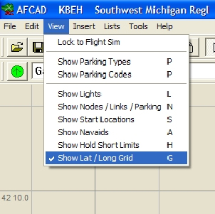 |
Note:
I print all my airport diagrams in portrait
layout. If the airport graphic is taller than it
is wide, I leave the latitude longitude lines
in. If it looks like I'll have to rotate the
image to get it to fit a portrait layout, I'll
generally omit the grid lines. If you leave them
in they become part of the basic graphical
representation of the airport, making them
difficult to remove later. It's your choice, and
this is the time to make it.
Zoom the AFCAD
image as large as possible without losing any of
it off the edges. If you chose visible latitude
and longitude grid lines, it is best to move the
diagram is far to the left of the screen as
possible without covering any of the grid
labels. (Right / Left Arrow keys)
|
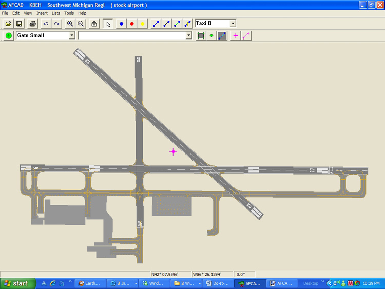
Make a screen capture of
the image. Leave AFCAD open at this point; you'll be
coming back to it.
Open your photo editor. Paste the image from AFCAD.
Rotate the image if necessary for your desired page
layout.
Crop the image. Try to maintain an aspect ratio (length
vs. width) roughly approximating your page dimensions.
It's not necessary to be exact with this, just eyeball
it for a rectangle that appears to have roughly the
proportions of a piece of printer paper. (below, left -
this one’s not exact, but it’s good enough)
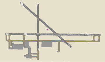 |
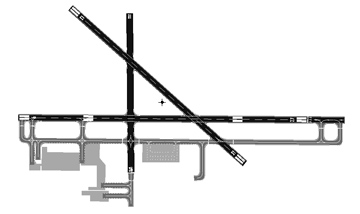 |
Transform the image to
black-and-white, and if necessary, adjust contrast and
brightness to suppress the background hue from AFCAD.
(above, right)
This is a good time to do the first save – I use jpg
format. It's OK to use the best resolution available --
file size will not be particularly large. Save often –
this is the only reminder.
Capture Airport
Information from FS
Open Flight Simulator. Go to the “Create a Flight” menu.
Select your airport. "Fly Now" (don't worry about
aircraft type, weather or time of day).
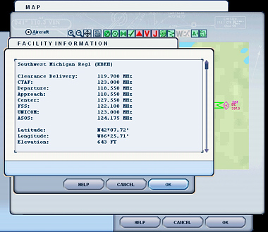 |
Press the “Map”
sim-icon. Zoom a couple of clicks, and select
the airport. Bring up the text box with the
airport information.
Highlight all the
text and copy it to the clipboard. You must use
Ctrl-C to perform the copy as there is no
right-click menu here. Be sure you scroll down
to get all of it.
|
Now open Notepad Crtl+V or
Edit - Paste into Notepad
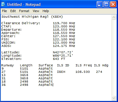
Close Flight Simulator
Add non-graphic elements to the diagram
Return to the photo
editor. Set the drawing color to black.
The next step is to begin adding the text elements to
the diagram. You may have to experiment with font sizes
to see what looks appropriate. I find some variation in
this from diagram to diagram. Good starting values are:
| |
Description |
Font |
| |
ICAO code:
|
16 |
| |
Airport name
and city: |
12 |
| |
Runway numbers:
|
12 |
| |
"N” for
North arrow: |
12 |
| |
Taxiway
designators: |
10 |
| |
Ramp labels:
|
10 |
| |
Other text: |
10 |
... adjust these as necessary to fit the required text
into the available spaces as you proceed. Once you have
a piece of text placed, drag it around and drop it in
the place that is most pleasing to your eye. There are
no rules for this.
 |
Note:
Regarding typeface
selection, tables and things line up better if
you use a fixed-pitch font, but variable-pitch
fonts are better if space is tight. This is a
judgment call. Common fixed-pitch fonts are the
Courier and Lucinda families.
If you want one, this is a good time to add a
North arrow. Most photo editors will draw an
arrow -- place a short one where you wish
(Hmm...do I need to say here that it should
point north? No, probably not.). Try to avoid
putting it in any large open areas of the
diagram; you may need those to fit in blocks of
text later. If you wish to use one, put an "N"
adjacent to the North arrow.
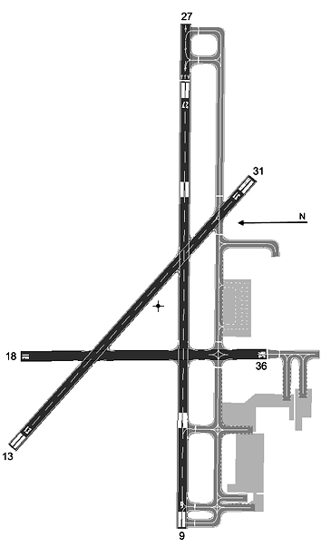
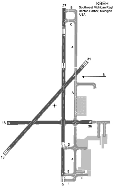
Place runway numbers at the ends of each runway.
Pay attention – this seems a little illogical at
first. It’s the reverse of the compass rose. If
you’re labelling Rwy 14/32 the “14” goes in the
north-west corner and the “32” goes in the
south-east.
|
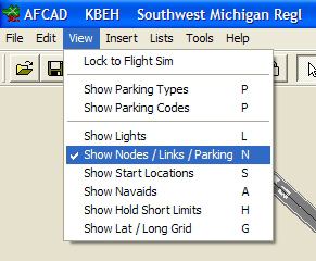 |
Return to
AFCAD.
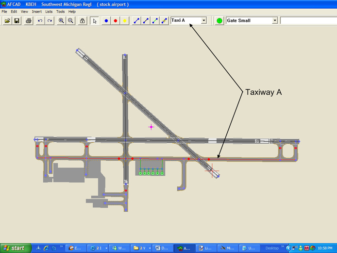
From the top-line menu, turn on links and nodes.
(View -> Show Nodes, Links, Parking). From the
list box in the toolbar, select the taxiways one
at a time. As each is selected its center-line
will turn red. Using these as a reference,
toggle back-and-forth between AFCAD and your
diagram in the photo editor and add the taxiway
designators.
|
 |
Note:
I try to keep the font size of the taxiway
designators a little smaller than the runway
numbers. There tend to be more of them and they
sometimes have to be fitted into congested areas
of the diagram.
Try to place them
so that there is no doubt as to which taxiway
each is intended for. It is desirable sometimes
to label a taxiway in several locations (see A).
As a last resort the designator can be placed in
a clear spot and an arrow used to point to the
referenced taxiway; I try to avoid this if
possible.
Put the ICAO code at the top right corner.
|
Add the airport name, and
the city and country just below the ICAO code. Some of
this can be copied in from the data you already have in
Notepad, but usually not the city and country. If you
don’t know it, you can get this from the Airport menu in
Flight Simulator or from the web.
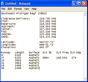
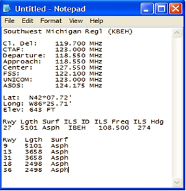
Return to Notepad. The remaining text we still need from
here tends to be in three logical blocks -- 1) latitude,
longitude and elevation, 2) radio frequencies, and, 3)
runway table. I try to place each of these into the
airport diagram as a separate piece, fitting them where
they go best.
Note: Usually it is necessary to reformat the
blocks of text so they will fit into the available areas
of the diagram. It is easiest to do so before copying it
out of Notepad. For instance, there are many extraneous
spaces after the colons in the first two blocks of text
that can be deleted to narrow the entire block, and some
of the labels can be shortened.
Also, you sometimes need to split the runway table into
ILS runways and the others. ILS runways have data in all
of the columns – the others do not. The latter can be
compressed into a much narrower table that may fit in an
otherwise unusable area of the diagram. If space is an
issue, break out the non-ILS runways into a separate
table using only the runway number, length and surface
type columns. If the table is still too large you can
compress it by changing “Runway” to “Rwy”, “Length” to “Lgth”,
“Surface to “Surf” or “Sfc” and delete spaces to bring
the columns into line.
 |
 |
|
Notepad data
before editing |
Notepad data
after editing |
Format each of the blocks and copy and paste them into
the diagram where they will fit best. Play with font
size if you need to here.
If you wish to, label the ramps with “GA”, “Commercial”,
“Cargo”, “Military” or any other designators you might
care to use. You can usually discern this by examining
the parking spots in AFCAD.
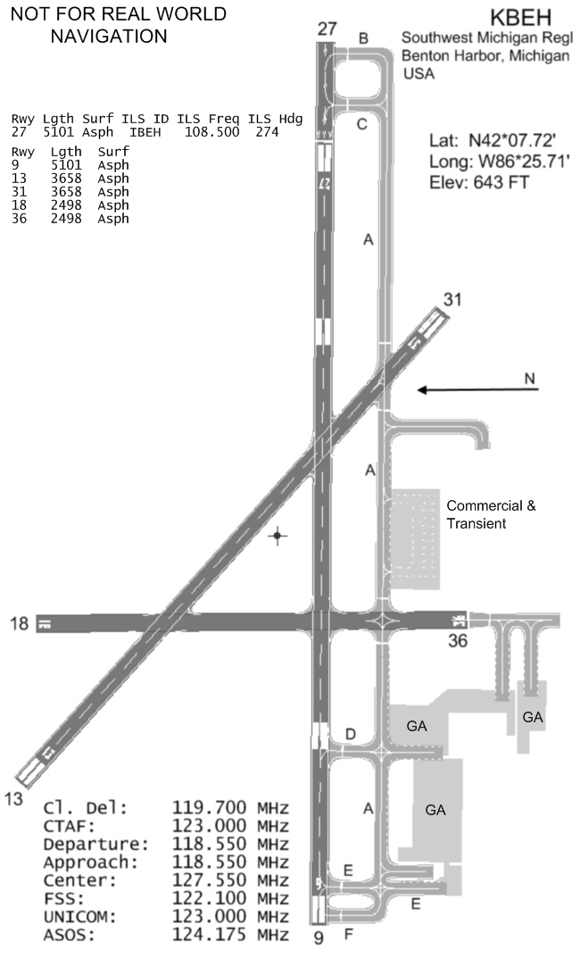
CONCLUSION
With some practice, you can easily knock one of these
out in about 15 minutes. This one had a few quirks. It
happened to have the long axis lying East-West, so had
to be rotated to fit my portrait format.
If I hadn’t cropped quite so closely at the Rwy 27
approach end (top) I’d have had room to put the ILS
Runway table across the top and thus could have used a
larger font size.
In this diagram I could have kept the runway table in
one piece as there was plenty of room for it, but I
split it out to show how I do that. I kept the Non-ILS
runway table in the same size font as the ILS table for
appearance sake, but there was plenty of room for the
Non-ILS data to be in a considerably larger font.
If you intend to share your diagram, or even think you
might, do yourself a favour and add a prominent “Not for
Real World Navigation” label. It seems incredible that
someone might actually use one of these in a real
aircraft someday, but stranger things have happened. You
can’t protect a fool from himself, but you can prevent
his widow's lawyer from making a victim of you too.
Back
to John's Section Home |