Introduction
7-Segment displays can be seen almost anywhere on a day-to-day
basis. Calculators, digital clocks, car thermometer displays,
DVD/Video players and watches are just some examples of devices
utilising segmented displays.
7-Segment Displays are named so because they are literally built
up from seven individual segments. These segments can be lit up
to contort the display into various letters and numbers. For
example, if all the segments are illuminated, the number “8”
will show. Please see the diagram below for more clarification.
Opencockpits, a Spanish Hardware manufacturer
and distributor, have allowed 7-Segment displays to be used
readily within your very own computer. They have even provided
the option to use these displays with your home flight
simulator; whether that be FS2004, FSX or X-Plane.
The Opencockpits Displays Card has been designed to control up
to 16 7-Segment display units and interface them to a computer
for use with Flight Simulator. This Card allows users to fully
manage segmented displays which feature so commonly in modern
aircraft cockpits.
7-Segment displays are connected to the card via an electronic
circuit, which can be simplified if you purchase some
Opencockpits specialised 7-Segment display PCBs (Printed Circuit
Boards). These boards allow for a much simpler and more
efficient connection to the Displays Card.
Product
Information and Purchasing
This product can be purchased from Opencockpits or The Aviation
Megastore for 33 Euros, plus additional VAT and Shipping charges
where applicable.
Judging upon personal preference only, it is cheaper to order
the IOCards series of products directly from Opencockpits.
Aviation Megastore tend to overprice on shipping, and also
charge a 5% fee upon all products purchased.
Please note, the Displays Card is NOT a standalone product.
Before purchase, one must own and have installed a fully-working
Master Card, also available from Opencockpits for around 55
Euros. It would be fair so say, therefore, that the Displays
Card actually “costs” around 90 Euros, because it is a
prerequisite to have a Master Card installed.
The product is advertised as boasting the following features:
First Impressions
After opening the box, I discovered that this particular interfacing card seems much simpler than the other cards available from Opencockpits range. The connecting pins that link between the displays and card are few, and the card seems very clearly subdivided into easy-to-understand sections.
The classic 40-pin IDC/IDE connector present in 90% of Opencockpits' products makes a reappearance, however this time represents a much simpler purpose. The IDC connector simply needs to plug straight into the Master Card through use of a ribbon cable; no soldering or wiring required! Once plugged into the Master Card, it should work straight away. See, I told you it was simple!
|
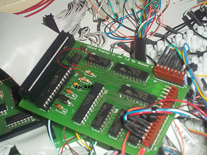
One interesting thing I noted was a series of jumper pins
located to the top-left of the card. Jumper Pins are literally
pairs of metallic pins that protrude straight from the card that
have a “jacket” over them.
This jacket can be “jumped” in-between to select various configurations. In this product's case, it selects between and identifies which card you are using (due to the fact that one can have up to four display cards connected to one PC, it is very important to distinguish between them). Setting Up In comparison with other Opencockpits Cards, such as the USBLCD Card, setting up is a breeze. Connection to the master card is done directly through an IDC Cable, and attaching 7-Segment Displays to the card is simply a matter of basic one-on-one wiring. |
 |
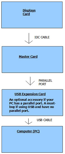 |
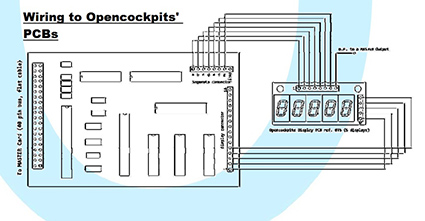
As you can see, the card follows a daisy-chain
pattern to connect to your PC. The beauty of the
Displays Card is that once it is connected to your PC,
absolutely no software is required to install the
product. Unfortunately, Opencockpits haven't quite developed a telepathic interfacing system just yet, which means the user will have to wire his/her card to his/her displays. At this point, there are two options. 7-Segment displays can be purchased globally from many online stores and local electronic shops. However, when purchased, you will literally receive just a 7-Segment display with several pins attached. Opencockpits have brought this a stage further. Available from their retail shop, specialised 7-Segment display units can be purchased which have already been professionally mounted onto a printed circuit board. This not only reduces the time invested in soldering the displays, but also makes to process much easier and much less intricate. The “pre-drilled” Opencockpits boards are also a godsend if you plan on using more than one 7-Segment display. This is because they are already slotted into a PCB and connected together through the board's copper tracks Alternatively, one would have to connect each individual 7-Segment display to one another by oneself. Opencockpits kindly supplied their printed circuit board 7-Segment displays along with the Displays Card, meaning that I did not have the misfortune of having to obtain and connect my own 7-Segment displays. Luckily, Opencockpits support both; wiring diagrams and instructions are provided both for those who purchased their own displays and for those who used Opencockpits segmented modules. Before connecting your display, we must ensure that the jumper pin (see above) is In the correct slot. If this is the first displays card you have purchased, then there will be no need to adjust anything, as it will already be in the correct position. T find out which position is correct for your card, please refer to the Opencockpits manual. |
I am very impressed that Opencockpits have
chosen the jumper pin system to distinguish between multiple
cards. Usually, these types of products require you to
solder a very specific wire to a particular pin upon the
master card; very messy and difficult to do. The jumper pin
system is effort-free and requires no soldering, wiring or
equipment.
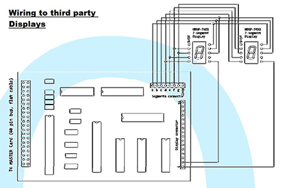
To wire our display, we must refer to the Opencockpits
manual circuit diagrams.
 |
 |
Once wired, we must test the card through
use of Opencockpits freeware software, available from the
“downloads” section of their website.
Testing the Card
The application controlador.exe, which comes bundled with
the installation of SIOC v3.71 (B1), is the main point of
communications for most of Opencockpits Cards.
Using this application we can control and test our
constructed 7-Segment Display array.
To start the application, navigate to the location of
controlador.exe (located in the main SIOC folder), and
simply double click on the green icon. This will bring up
the following GUI:
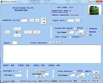 |
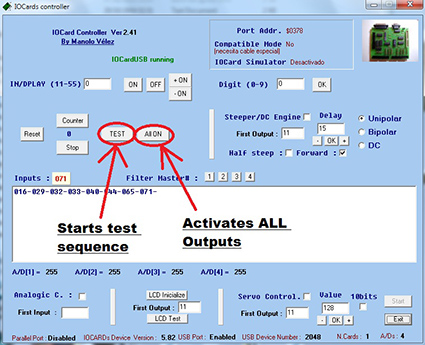
At first, the Controlador program may seem
overwhelming. It is a powerful testing utility and
can be used to control many things, not just
7-Segment displays. However, for the purposes of this review, we will be concentrating on just four, click-able buttons. Before we can test anything, we must click on the “Start” button which resides in the lower-right corner of the program. Once clicked, the application will come to life and offer all of its features. Once started, there are two options in regards to testing the card. The first, and simplest, option is to click on the “ALL ON” button. This will activate all available outputs and turn everything on. This includes any LEDs you may have connected to your Master Card. If “ALL ON” is selected, all 7-Segment Displays will be written to with an “8 Digit”. |
|
When this test is activated, my 7-Segment display units look like this: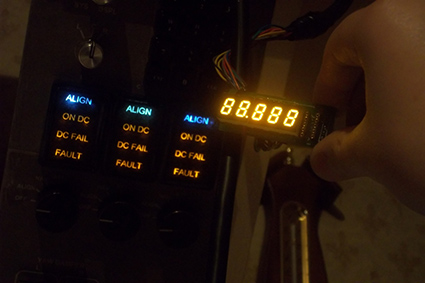 |
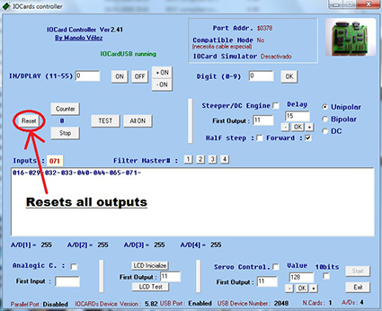 To de-activate all outputs, and to turn the 7-Segment displays off, simply click on the “RESET” button. This will kill anything that is turned on and linked to the Master Card. |
|
Alternatively, a more rigorous testing routine is available. Clicking on the “TEST” button starts a special routine in which outputs are activated in a sequential order. The 7-Segment displays will, one-by-one, alternate through numbers 0-8 before finishing and remaining on number 9. Clicking the test button also activates a “Counter” which will begin after your displays have been written with a number 9. Similarly to the “ALL ON” function, the test sequence can be terminated by clicking the “RESET” button. It is recommended that your card and 7-Segment displays be able to perform the above tasks before beginning any programming using SIOC. I always find the controlador.exe program a very useful and detailed testing utility. I don't just use it for my 7-Segment displays; it is used throughout my cockpit to test everything from CDU execute lights to pressure warning annunciators on my overhead panel. |
 |
Programming with SIOC
<Please note, this portion of the review contains technical
references and practices. As a result, you may wish to omit
this section of the review. For more information, please
visit Opencockpits' website, or download the SIOC manual;
available at the end of this review.>
Now that we have tested both our card and displays, it is
time to approach the advanced yet incredible world of SIOC
scripting.
SIOC is the software interfacing program for all of
Opencockpits' products. It is similar to the controlador.exe
program (read above), however, instead of receiving commands
directly from you, the user can tell SIOC to transmit and/or
receive specific data from Flight Simulator
(FS2004/FSX/X-Plane). To use SIOC, a copy of FSUIPC
(registered or unregistered) is required.
SIOC can be found in the same installation folder as the
controlador.exe program (see above).
To implement our 7-Segment displays into SIOC, we must write
a few short lines of script or “code” as it is sometimes
known. This script can be written in any text editing
program, but notepad is preferred due to simplicity and
accessibility.
For testing purposes, I will demonstrate a simple script
that will enable our 7-Segment displays to show the current
Indicated Air Speed (IAS) of our aircraft in FSX.
This is the test script I wrote in notepad:
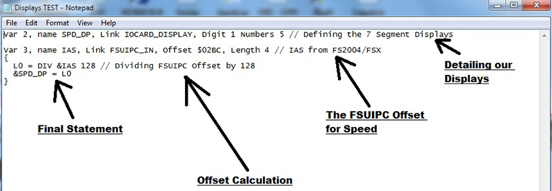
I have annotated each part of the script but I shall analyse
them in more detail below. Please note, this section of the
review is purposely over-detailed and some portions of the
script literally look as simple as they seem.
Also note, wherever there are two forward slashes (//),
anything after the slashes is completely irrelevant and
provides no contribution to the script. The two slashes are
often used if an author wants to make notes on a particular
“snippet” of script, as anything he/she types after the
slashes will not make a difference in the script.
“Var 2, name SPD_DP, Link IOCARD_DISPLAY, Digit 1 Numbers 5”
This line tells SIOC that we have five 7-Segment Displays,
beginning on “Digit 1”. “Digit 1” means that the first unit
in the series of the five displays is wired to pin one on
the card. NOTE: Pin one is NOT the first pin on the card. It
is in-fact pin ZERO (Opencockpits interfacing cards start
their numbering from zero, not one. This means that zero is
the first, one is the second, and so on).
Pin zero on my card is connected to an unrelated display, so
I have ignored this and told SIOC to start from pin/digit
one. I have also stated that I wish to use FIVE 7-Segment
displays. This means that SIOC will display my Indicated Air
Speed from FSX within digits 1-5.
You may also notice the “Var 2” written at the start of the
statement. “Var” is short for “Variable”, and a variable is
required in every SIOC “declaration”. Variables are, as
their name suggests, “things” that can vary (ie; be in one
state or another). Everything in a cockpit is a variable.
For example, a switch can be on or off. An annunciator can
be illuminated or distinguished. A gauge can be pointing to
one value or another value. This is why our displays are
variables; they can be one number or another number.
To declare a variable in SIOC, simply type “Var”, a space,
then any number between 1 and 9999. It does not matter which
one you choose, as long as it is not in use by other
variable.
The “name” part of the line (“SPD_DP”) is literally a name.
It is advisable to give variables names so you can refer to
them later in your script. It does not matter what you call
them. Naming variables is, however, completely optional.
“Link IOCARD_DISPLAY” tells SIOC that our variable is linked
to an Opencockpits Displays Card.
“Var 3, name IAS, Link FSUIPC_IN, Offset $02BC, Length 4”
As we have already discussed the “Var” and “Name” sections
of scripts, we shall move on to the phrase “Link FSUIPC_IN”.
“Link FSUIPC_IN” is how to tell SIOC that we wish to read
(extract data from) something from the FSUIPC program. This
is of course correct as we wish to extract the data value of
our aircraft's IAS. Similarly, “FSUIPC_OUT” means write to
an Offset. We would use FSUIPC_OUT if we were interfacing
something like an autopilot switch. However, since we wish
to get an output working, FSUIPC_IN will suffice.
Although we have told SIOC we wish to read data from FSUIPC,
we have not specified which particular data. This is where
we enter a four-digit code, or “Offset Number”.
Offset Numbers can contain both numbers and letters. Each
code is unique to each individual offset. Within FSUIPC,
there are offsets for almost everything. Since we want our
displays to hold current aircraft speed, we shall use Offset
02BC, which represents IAS. Please note, all references to
airspeed within this review are in Knots.
In SIOC, one must place a dollar symbol ($) before each and
every offset code.
“Length 4” tells SIOC that offset $02BC has a length of 4
bytes. Different offsets have different byte values. For
example, offset $0BC8, representing an aircraft's parking
brake position, has a length of 2 bytes.
“L0 = DIV &IAS 128”
This line is a calculation. When SIOC receives the airspeed
data from FSUIPC, it is multiplied by 128. This is of course
an inconvenience, as SIOC may interpret an aircraft going 75
Knots as 9600 Knots!
To counter-act this, we simply divide the multiplied value
by 128. This will give us our correct value. To do this, we
use the “DIV” command, followed by the name of the variable
in question (remember, we called the airspeed variable
“IAS”). To refer to the airspeed variable, we type IAS
preceded by an ampersand symbol (&IAS). The ampersand symbol
must be written before each-and-every reference to a
variable name.
The “L0” at the start of the line is what we call an
“Integer/Float Internal Variable”. Internal Variables
temporarily hold the value of whatever they are assigned.
Anything after the equals sign in a statement using an
Internal Variable will represent it. These float variables
do not have to be “L0”, they can also be “L1” or “L2”. For
example:
L0 = 159
L0 will now equal 159, and we can recall L0 in another line
of script, for example:
&Cheese = L0 + 15
The variable “Cheese” will now equal 174, because L0 (159) +
15 = 174.
In our Displays script, L0 holds the value of our aircraft's
airspeed divided by 128. Remember, airspeed must be divided
by 128 before it can be used in SIOC, or else we will
receive very adverse readings.
Internal Variables are often used when more than one line of
calculation is required. This is because SIOC cannot handle
more than one calculation per single line, so we must
“hand-down” the value from one line to another.
Please note, the bracket above this line is very important.
“Curly” brackets are always used to “execute” a command.
Whenever we want something to happen in SIOC (for example,
illuminating an LED), nothing will happen unless it is
enclosed within a bracket. Whenever an event takes place
within SIOC, it is the script within the brackets that is
executed.
“&SPD_DP = L0”
This line is identical to the operation performed in the
above paragraph. The only difference is, instead of telling
L0 to equal something, we are telling something to equal L0
(a sort of backward logic).
We tell the variable “SPD_DP” (remember, this is the name we
gave to the 7-Segment display unit) to hold the value of L0.
Since L0 is our calculated IAS value, the variable SPD_DP
will show the perfect airspeed of the aircraft in Knots.
Note the bracket below this line. It has an equal function
and importance to the aforementioned opening bracket,
however this time it closes the execution (hence anything
between the brackets is executed).
Compiling our SIOC Script
Whilst our notepad version of our SIOC code is complete, it
is useless unless we actually “compile” it.
To compile our script, we will double click on the SIOC
program icon. The following window should pop-up:
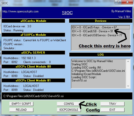
People using the USBExpansion Card (which, as
previously mentioned, is necessary if using a 21st Century
USB-Equipped PC), should check that the entry “IDX = 0 – IOCard
USB – Device = X” is present. Please note, number “X” is
different for every user and depends on which USB port the card
is plugged into.
To continue with the compiling process, hit the “CONFIG” button.
This will bring forth the following window:
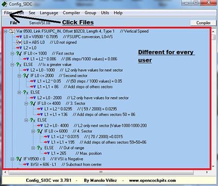 The area enclosed within the red box is unique to every user, and depends on which SIOC script you are running. Since I have a very large script which caters for half of my Boeing 767 cockpit, this area takes up over 1000 lines and contains many complex calculations. Since we are just configuring a simple 7-Segment display, we can completely ignore this area and just click the “FILE” button. This will make the following drop-down menu appear: |
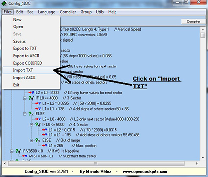 After clicking on “Import TXT”, a file selection box will appear, requesting the location of our notepad 7-Segment Displays script. Since I saved my script to my desktop as file “Displays TEST”, I just navigate to my desktop and load the notepad file. |
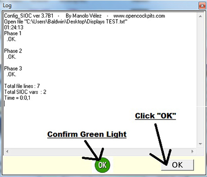
After locating your file, click open. If the script has been successfully compiled, the following window will appear:
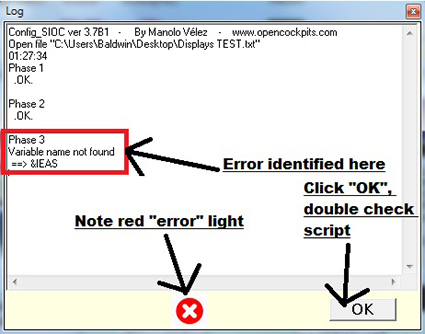
However, if, for whatever reason, there is
an error within your SIOC notepad file (maybe a spelling
error, missing bracket, calculation problem, etc), the
second window will appear. In this case, I have purposely
spelt “&IAS” wrong, and instead written “&IEAS”.
As you can see, SIOC has correctly identified my error. If
this should happen, click OK, close SIOC, and re-check your
notepad coding for anything that may be causing the problem.
Assuming the file has compiled correctly, and the “OK”
button has been clicked, SIOC will settle back to the
following box:
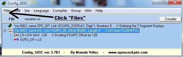
After confirming that the file has compiled successfully, click on “FILE” to access the drop down menu:
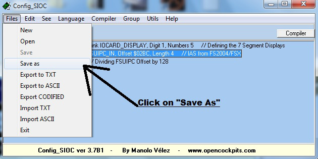
This time, we shall click on “SAVE AS”.
This will, yet again, bring forward another file selection
box. Since we are saving this file as an exported SIOC file
(file extension “.ssi”), we will navigate to the location of
our main SIOC folder. On my PC, running Windows 7 64-Bit, it
is located at:
My Computer\C Drive\ Program Files (x86)\IOCards\SIOC.
The file name must be saved as “sioc” (.ssi). After naming
the file, click on “SAVE” to confirm the process. A box may
appear, asking you if you wish to overwrite this file. Click
“YES”. After clicking “YES”, the entire process of making,
compiling and running our SIOC script is complete.
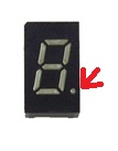
| Decimal Point
(DP) LEDs Most 7-Segment displays, especially the ones available from Opencockpits' shop, contain Decimal Point LEDs. DP LEDs are literally LEDs that form a small “dot” under each segment, acting as a decimal point. These are completely unnecessary for the operation of the card and getting numbers to display, however, they are vital if you wish to display something such as a radio frequency. This is because most frequencies come with an attached decimal, such as “115.29”, “109.22” or “120.20”. Note the position of these Decimal Points, highlighted here in red: |
 |
To get these DPs working, we will actually
have to bypass the displays card and connect it directly to
an output of the master card, just like a normal LED.
Unfortunately, the Opencockpits 7-Segment PCBs do not cater
very well for this. The Decimal Point terminals are just
“stuck through”, and are not connected to any copper trails
on the card. In fact, to connect to the DPs, one must solder
one's own wires from the decimal to the master card.
Furthermore, I'm a little disappointed that there isn't much
in the way of accommodating the Decimal Points. Actually
having to connect the terminals to the master card is a bit
of a pain; I always find it is much easier to keep
everything “neat” and on just the one interfacing card. As
such, it may have been a good idea to put a few LED outputs
or similar onto the main PCB of the displays card.
Theoretically, these small DPs would blow if we connected
them to the master card, as it appears to give a continuous
5V output, way to high for such an application. However, the
opening and closing of logic gates provides a pulsed
voltage, which does not damage the DPs in any way.
When connected to the master card, they can be treated
identically to any normal LED. Both SIOC Software and the
master card will see no difference between the DP LED and a
normal one, so the user can test and script his/her LED
normally.
Controlling Brightness
To control the brightness of any 7-Segment displays through
the card, one must implement a few lines of special SIOC
code within their script.
Writing the value -999994 followed by digit N will set the
brightness of the chosen display. This is where digit N is a
number between 0 and 15, with 15 being the brightest
possible value.
Again, this is totally optional and I myself have not
bothered using these settings at all.
Documentation
Manuals for the Displays card are available at the product
page, found at www.opencockpits.com. These can be downloaded
in PDF format.
The documentation is largely informative. Guides for wiring,
installing, and testing the card are all present within the
7 page manual.
Diagrams are included to aid the sometimes tricky processes
of circuitry and soldering. A fully annotated diagram can
also be found; detailing the card's components.
However, whilst the manual will provide the user with enough
to “get going”, there are sections which are, quite frankly,
very confusing. For example, the sentence:
“Due to the operating mode of the card (multiplexed) the
tension overloads in the Display's LEDs will never occur,
because what these receive are tension pulses and not a
continuous tension, avoiding any segment of the display to
blow.”
This paragraph left me bewildered. It was not until I found
out that the Spanish word for “voltage” is “tension” that
everything made sense. It is occasional errors like these
which can lead to initial confusion, and, although they are
easy to understand once you do a little “digging”, do not
help in aiding the understanding of the already technical
product.
For those of you who wish to know, that paragraph actually
refers to the pulsed output given to the DP LEDs (see
above).
I also found the paragraphs regarding SIOC scripting a
little uninformative. For example, the section which
explains how to assign brightness to a 7-Segment display,
which just gave a short explanation and an example which did
not help me understand the matter any further.
Advanced scripting and
Lekseecon
Nico Kaan, a user of SIOC from the Netherlands, has
developed a program called Lekseecon which silently runs in
the background. It connects to SIOC via the IOCPSever
installed with SIOC.
This program works exclusively for the Level-D 767, and the
upcoming Level-D 757 add-ons for FS2004 and FSX. It provides
pre-defined variables and comes with a very, very detailed
manual guiding you through each step.
These pre-defined variables cover everything within the
Level-D 767 add-on. Every switch, annunciator, lever and
knob can be adjusted using Lekseecon, and similarly the
state of each of these can be received from the program and
transferred over to SIOC.
Scripting in SIOC is much easier with Lekseecon, but is
still fairly tricky and not really necessary to mention
within this review. However, I have successfully utilised
the Lekseecon program along with an advanced SIOC script to
produce a rather outstanding result with the Opencockpits
displays card.
Opencockpits kindly supplied some 7-Segment display units,
along with the card itself, for this review. These displays
are being used in my cockpit to provide a variety of Boeing
767 overhead features, such as fuel loading and external
temperature.
However, I have already configured one 5-Unit 7-Segment
display to hold the true value of the Left HF (High
Frequency) Radio found on the upper-left area of the
overhead panel, column two.

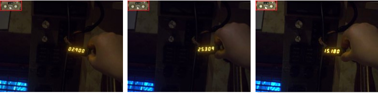
Using Lekseecon, SIOC and an advanced SIOC
script, I have managed to get my 7-Segment display to
accurately and currently display the Left HF Unit Frequency
in real-time.
The script covers many important aspects. For example, when
my Boeing 767 Batteries are turned off, the 7-Segment
displays remain completely dead unless power is supplied to
them. Furthermore, the script caters for a fully-functioning
decimal point within the display.
Also included within this script are support for rotary
encoders and rotary switches (to tune and select between
frequencies). This script was kindly produced by Nico Kaan
and can be found within his Lekseecon installation.
I am very impressed with the results of this script and the
displays card. Please look below for photographs of the
interfaced displays. The highlighted box in the top left
corner is what I can see on my (simulated) Level-D 767
add-on in FSX.
Conclusion
The Opencockpits displays card is the definitive choice for
those wishing to use 7-Segment displays within their
cockpit. I have become to consider it a cockpit staple, as
around 50% of cockpit displays are represented through
7-Segment units.
It is very flexible and works flawlessly if using the
provided SIOC software. The ability to control brightness
further adds to the card's accessibility.
The card is easier to set-up than other Opencockpits cards,
but the documentation is a little off-putting at first. With
a little translational tweaking and a bit more effort, the
manual could achieve great things.
I also think the cater does not cater very well for those
wishing to use decimal points within their cockpit. Although
I appreciate it seems easy to just connect the LEDs to a
master card, this is a very fiddly process which can be
difficult for those new to soldering.
The card provides fantastic value for money at just 33 Euros
+ Shipping.
Personally, this card is my joint favourite card, along with
the Opencockpits USBServos Card. Although I must admit, the
displays card is much easier to get working than the
USBServos card.
Overall, this is a brilliant product and, in future, I will
not hesitate to purchase some more for my Boeing 767
Cockpit.
![]() Verdict
Verdict
Pros:
Cons:
Mutley's Hangar Score: 8.5/10
Jack
Whaley-Baldwin
Review machine Spec: Core i7 920 OC @ 3.8 Ghz |
6Gb Tri-Channel DDR3 Ram |GTX285 Graphics |Windows 7
64bit Home Premium
|
|